Back to U-Joint Page 1

Is a Constant Velocity Joint Really Constant?

Constant velocity as the name implies means the output should exactly mirror the input. As we know, nothing is perfect, and neither is the CV joint. The CV joint is really designed for perfect phasing at only one running angle. If the joint is ran at other angles, there will be some phase error, but is still very little. My guess is that the Toyota CV joint is ideal at 6 degrees.

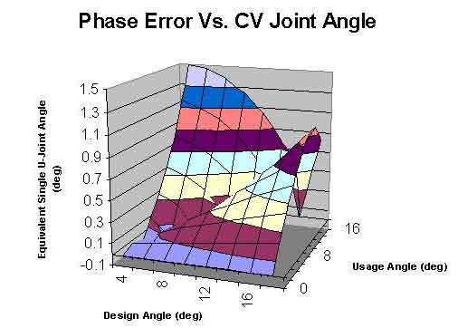
But how much phase error is there if CV joint is ran at other angles? The graph below shows the answer. It assumes a CV joint is designed for running at 6 degrees. This means, the joint would be perfectly constant at 6 degrees with no phase error. The horizontal axis is what angle that the CV joint is going to be used at. The vertical axis is the amount of phase error. It would be meaningless to give a number for the phase error if you can't put that number into perspective. Therefore, the vertical axis is put into persepctive of a single ujoint. That means an error of "1" means your CV joint has as much phase error as if you were using just on regular ujoint running at 1 degree. As seen in the graph below, obviously if the CV joint is used at 6 degrees, there would be no phase error. There is a dip on the graph at 6 degrees. If the same CV joint is used at 14 degrees, then there would be as much error as if you were using a single normal ujoint at 1 degree.
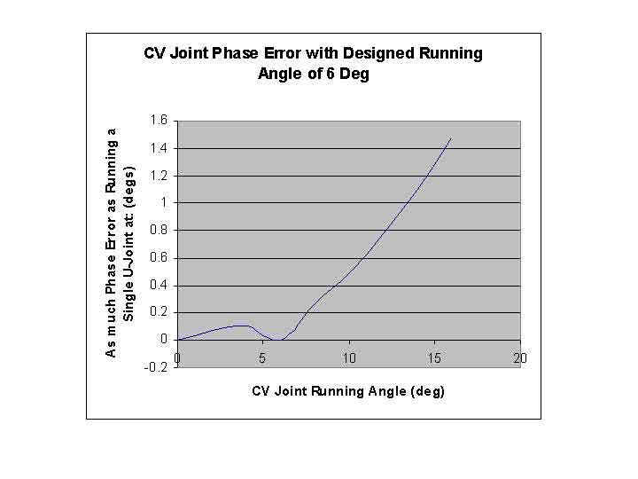
Figure-1

See spreadsheet on calcuation of CV joint (The cells in green can be changed to do "what if" scenario. All other cells are locked and can't be changed)

Prove positive: Page on mathmatical derivation of U-joint

For most rigs, the CV joint error is not significant enough to cause a problem. However, for shor wheel base vehicles that are lifted or with extreme lifts where the CV joint is required to run at high angles. With those angles, the phase error would be more significant. At high angles of around 30 degrees, the error would be as if a single ujoint was running at 5 degrees. A normal stock CV joint would have to be clearanced to run at such angles, or you have to order a custom CV joint.

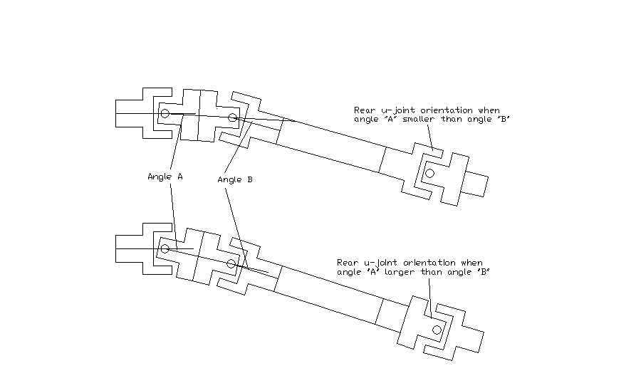
Let say you do have to run a CV joint at high angle, or you are the perfectionist type who want the driveline to be vibration free at 100mph. Question is if anything can be done about the CV joint phase error. Answer is yes. There are two ways to dealing with CV joint phase error:

It can be mathmatically proven that the error from the CV joint can be completely canceled out with the rear U-joint if the U-joint is oriented as per the graph below. For example, if the CV joint is designed for 6 degrees, and is used at 10 degrees, there will be a equivalent of .5 degrees of error. To solve the phase error, just rotate the rear axel so the u-joint is running at .5 degrees. It does not matter if the pinion angle is up or down, the cancellation effect of the u-joint is symetrical.

Second question is how do you know what is the ideal angle of the CV joint. No problem if you have access to the CV joint production drawings. However, if you don't, it can be measured. Use an inclinometer to measure the angles of the two u-joints inside the CV joint. Take the difference of the angles. What is left over is the amount that you have to correct with the rear pinion.


Below is a 3D graph of various design angles and usage angles. The axis that goes left and right is the design angle. Base on the internal geometry of the CV joint parts, a CV joint is designed to run with absolutely no error at the design angle. The axis that goes into the page is the usage angle. This is the angle that the CV joint is going to be run at on the truck. The vertical axis is the phase error of the CV joint converted to a meaninful number. The number indicate the amount that the rear pinion would have to be angled if it were to correct for the CV joint phase error.

Figure-2

There is a fold in the middle of the graph. That is because when the CV joint is ran at the designed angle, there is no phase error. The graph at that point drops down to zero. At 0 degree usage angle at the front of the graph, there is no phase error. Since the CV joint is straight, it acts just like a shaft. At higher usage angle, the error increase exponentially.


To cancel the phase error, when you assemble the driveshaft, make sure that the rear U-joint is oriented base on which u-joint in the CV joint has the larger angle. Otherwise, you will be increasing the error rather than cancelling it.

Figure-3


Step by Step Instruction on How to Correct CV Joint Phase Error

Here are the step by step instruction on how to cancel out the CV joint phase error.

Figure-4

  1. Lift the rear end of the truck so that the wheels are free to rotate. Lift from the rear axle and not the frame so driveline is still at normal running angle..
  2. Rotate the driveshaft so that the bearing cap on the front u-joint of the CV joint is facing the ground.
  3. Use an inclinometer on ujoint bearing cap at "1" to measure the angle of the input shaft. Place a socket or some parallel object on the u-joint bearing cap to extend the cap so you can get a better surface to place the inclinometer. Use an inclinometer with accuracy of at least .1 degree. A plastic ones at the hardware store works just ok. The digital ones are much better, but they cost over $100. If you don't have a very precise measurement tool, you can always measure many times, say 30 times and take an average. Statistically, you will get the same answer but is much more time consuming.
  4. Measure the angle of bearing cap "3" the same way as "1" to determine the angle of the tube of the driveshaft.
  5. Rotate the driveshaft 90 degrees so that the middle two u-joints bearing caps are facing the ground. Use the inclinometer to measure angle of bearing cap "2". Since the two ujoints in the middle are at the same angle, you can pick either one to measure. This is the angle of the center section of the CV joint.
  6. Subtract angle "2" from angle "1". Ignore the negative sign if there is one for the result. This is angle "A".
  7. Subtract angle "3" from Angle "2". Ignore the negative sign if there is one. This is angle "B".
  8. The difference between angle "A" and angle "B" is the CV joint error.
  9. Correct this error by setting the rear pinion base on calculation in the spreadsheet. Open the spreadsheet. Go to the "CV Joint Correction" page by clicking on it at the bottom of the page. It should be already on the page when you open it. Enter the measured angle A and B in the green box. Get the result in the yellow box. Here is the same spreadsheet but in older 5.0 version. If you want the formular, here is it.
  10. Orient the rear u-joint base on whether angle A is larger than B or vice versa. See figure 3.
  11. Rear pinion angle can be rotated either upward or downward for the correction. Either way will cancell the phase error. However, since during acceleration, the rear pinion will be rotated upward by the reaction of the rear wheels, correct this effect by rotating the rear pinion down an additional .5 degrees. During driving, the rear pinion will then be at the perfect angle.
  12. Enjoy your smooth ride knowint that the u-joint phase are completely matched.

Page 3 Back to the 2 U-Joint shaft: What causes the limitation for a 2 U-Joint Driveshaft?


Back to Home Page