The Genius has a switch on the board that go between 3 axis and 6 axis mode. See video of the 2 modes on youtube. Everyone agree 3 axis give a very stable helicopter for 3D flying. 6 axis is suppose to be self leveling. However, there has been some issues with it.
1. Helicopter drift strongly to the left at high rotor speed. Even full right aileron sometimes cannot correct for the drift.
2. Even at low speed, there is a dead band where the self leveling is not that sensitive, so helicopter is either drifting slightly to left, right fwd or back. When you hold onto the helicopter while the rotor is spinning, you can see the swashplate jittering. Is constantly hunting.
This fix will solve the high rotor speed issue and reduce the dead band. The main issue with the accelerometer is vibration. Fix is to isolate the receiver from vibration.
The idea for the 6 axis fix came from babblin5 in post here. He tried to trim away the foam in front of the receiver, and it fixed the drift issue for him. Unfortunately, ScottAlly posted here that with the foam trimmed away at the front, it made the carbon fiber plate holding the receiver weak. This fix tries to address both issue by leaving the front foam in place for strength and cutting away middle foam for vibration.
There has been heated debate on RCGroup on what cause 6 axis issue. Currently, there are 2 camps. One is tilt of the receiver cause 6 axis issue. Second is vibration. The third camp claim leveling of helicopter cause drift. But everyone agree that is not the cause.Evidence:Here is a youtube video on proof that vibration affect stability in 6 axis mode. I believe the extreme drift is related to vibration. For sure, my helicopter went from demon posessed extreme left drift that can't be controled to best helicopter ever after this fix.
Dado099 mentioned in his post that this mod worked for him, and was stable even with high speed of the brushless motor. However, others were not able to see any difference after this foam mod. (I did not get any details on what was done and what was the before and after of the mod, so can't comment on the failures)
What this will fix and what it will not:
This will fix the extreme left that even full right stick will not compensate. It will not fix any small drift. Small drift can be trimmed out or by tilting the receiver slightly. (Not so much that the gyro axis no longer parallel with helicopter mast. This will also make the helicopter more precise.
This will not fix the random drift that the helicopter have. The 6 axis leveling is not so precise that the helicopter stays in one place indefinitely. It will eventually drift off after a second or so. This is not one of those 4 rotor flying machine with inertial measurement unit and GPS in it nor is this a coaxial.
Pro: Fix the extreme left drift.
Cons: With the softer foam, receiver is more likely to be tilted differently during each flying session. Do have to trim it with the trim during each flying session. But if the helicopter is not stable without the mod, you would have to trim it all the time anyway.
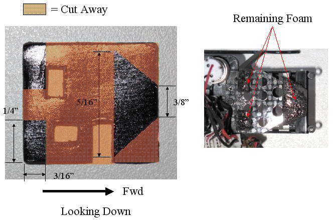
Unscrew the 2 screws behind the receiver board holding the piece of carbon fiber plate that the foam is stuck to. Helps to unplug the motor first. If you are careful, you can leave the rest of the wires pluged in. Slowly peel the foam away from the receiver. Starting at one end and working to the other.
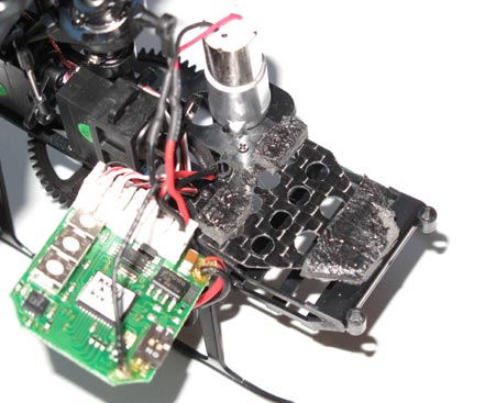
Cut away the foam as shown below. Be sure to leave the front still sticking to the battery box so the receiver is not only held in from the back. The remaining foam should still be plenty strong to hold the receiver in place during a crash.
When putting the canopy on, be sure to check that the canopy does not touch the receiver. The canopy acts like a soundboard at high rpm. If it touch the receiver, is possible for it to transmit vibrations to the receiver and cause issues no matter how soft the foam is. Put a piece of foam between receiver and canopy if necessary.
See youtube video on stability after fix summary.

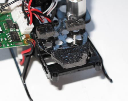
After cutting away portion of the foam.


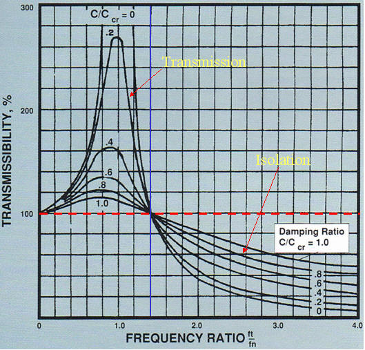
The curve above is the vibration transmission chart. The horizontal axis is the frequency ratio. For our purpose, this is the stiffness of the foam holding the receiver. Softer the spring the higher the frequency ratio number. A more accurate meaning is the more soft the foam or spring holding the receiver, the more to the right. The higher the frequency that the helicopter vibrates at, then also the more to the right. The vertical axis is transmissibility. That is how much vibration gets transmitted to the receiver from the frame. The red horizontal line is at 100% transmissibility mark. This means all the vibration gets transmitted to the receiver. That would be bad, but things can get even worst. To the right of the blue line the curves goes up. This is resonance. This means the receiver vibrates greater than the vibration of the frame. This is very bad. If the foam gets infinitely stiff, then that is frequency ratio of 0. Here you are at 100% transmissibility. That makes sense. If the foam is rigid, then all the vibration gets transmitted to the reciever, so 100% transmissibility.
We want to be on the right side of the blue line. This is the isolation region. This means there is less vibration going to the receiver.
Note that we don't know where we are at on the curve, but the important thing is the trend. The way the helicopter operate suggest we are to the left of the blue line. As vibration frequency gets higher as in higher rotor speed, helicopter goes into resonance range, and stability goes out the window. Result is helicopter goes uncontrolled to the left. Regardless, the important take away from this curve is you want the foam to be as soft as possible so you are to the right of the curve. Obviously, not so soft that you completely isolate even normal flight movement, but you will never get there, so there is not much worry about that.
Note that there are multiple curves on the chart with different damping ratio. The word damping has nothing to do with damping the vibration. This is the damping of the material whether is foam or spring you use to hold the receiver. Every material has some damping. Tuning fork for example has very low damping. Hit it and it rings for a long time. Foam on the other hand has high damping. Tuning fork made out of foam would never ring. When you press on a foam, it returns slowly, so it has lots of damping. Damping is important to note because in the isolation region, notice the higher the damping ratio, the higher the vibration that gets transmitted to the reciever. This is opposite from what we think. We always think more damping foam means less vibration to the receiver. Is the opposite. We are using foam, so damping is probably greater than .8. Most likely even higher than 1. So we are not isolating as much vibration than say a material that have lower damping ratio like steel coil springs.
A steel coil spring usually have a damping of around 5%. On the chart above, that would give you much better vibratio isolation than using foam. That could be an experiment to see if the Genius can be even more stable using say 3 coil spring to mount the receiver.
You will probably ask, and I did too, if foam is not as good as a coil spring in isolating vibration, then why do we use wrap foam around electronics to protect them from crashes. The difference is this chart is about periodic vibration. That means is a consistent vibration like a washing machine, an engine or helicopter. Crash is a one time even. In a crash, you actually want no damping on compression, but damping on rebound so you don't get double the hit. Some memory foam does that. However, when you have periodic vibration, damping hurts you because damping jerks the receiver around rather than isolate it.